KAPDEC® | Elite STEM Learning Platform | https://kapdec.com
Unit: Electric Circuits
Chapter: Resistivity, Resistance and Capacitance
Reference: AP Physics Algebra, Electric Circuits, Resistivity, Resistance and Capacitance, Electric Current Drift velocity, Relation between current and drift velocity Ohm’s law, Resistance, Resistivity, Conductivity and conductance, Current Density, Mobility, Resistors, Internal resistance, Capacitor and Capacitance
After studying this chapter, you should be able to,
- state Ohm’s law and distinguish between ohmic and non-ohmic resistances;
- obtain equivalent resistance for a series and parallel combination of resistors;
- state the capacitance
Electric Current:
The net charge flowing across a given area of conductor per unit time is defined as electric current.
I = Q/t, S.I. unit of current is Ampere (A).
A steady current is generated in a closed circuit where electric charge moves from lower to higher potential. Electromotive force or emf is the work done by the source in taking the charge from higher to lower potential energy.
Drift velocity:
The free electrons drift with some velocity towards the positive terminal when a potential difference is applied across the ends. The average velocity with which the electrons move is termed as drift velocity.
Drift velocity Vd = eE/τm =eV/τml
Where e = charge on the electron
E = Electric field intensity
V = Potential difference across the ends of the conductor
t = Relaxation time
m = Mass of electron
Relation between current and drift velocity:
Current is directly proportional to the drift velocity. I∝ Vd When the number of electrons is less, the current is less so the drift velocity is small. When the number of electrons is large, high current flows so the drift velocity is large.
Ohm’s law:
The voltage across the ends of the conductor is directly proportional to the electric current flowing through the conductor.
V ∝ I
Or
V = IR, where R is the electrical resistance of the conductor
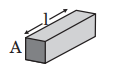
Resistance: The property that resists the flow of current through any conductor is called the resistance of the conductor.
R= V/I
It varies directly with the length of the conductor while depending inversely on the area of cross-section of the conductor.
R= ρl/A , ρ being the resistivity of the material of the conductor
Source: Kapdec.com
Fig.: Resistance in a conductor
Resistivity:
It depends on the nature of the material and temperature. It is also termed as specific resistance.
ρ =mne/2τ
gives the relation between resistivity and relaxation time
There is an increasing order of resistivity as we go from metal to insulator.
ρmetals<ρsemiconductor<ρinsulators
Conductivity and conductance:
The reciprocal of resistivity is conductivity (s).
σ =1/ρ and its S.I. unit is W–1m–1
The reciprocal of resistance is the conductance of the conductor. Its S.I. unit is mho.
Current Density:
The amount of charge flowing per unit area per second is called the current density. J = mqvd, where vd is the drift velocity of the charge carriers, n is the number of charge carriers and q is the charge. The relation between current density and conductivity is J = σ E.
Mobility:
Mobility is the ratio of drift velocity to the applied electric field. Mobility is symbolized by m.
Its S.I. unit is m2 s–1V–1.
Resistors:
The objects which resist the flow of charge are called resistors which can be of two types, i.e., wire-bound resistors and carbon resistors. Resistors can combine in two different ways; either in series or in parallel.
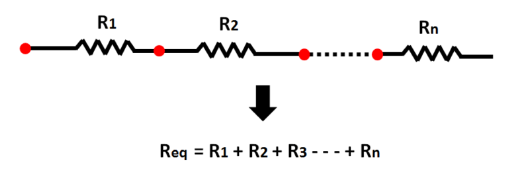
- Consider n number of resistors connected in series, then the combined resistance will be as follows:
Source: Kapdec.com
The same amount of current will flow through each resistor connected in series while the potential difference would be different for every resistor.
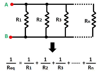
- Consider n number of resistors connected in parallel, then the combined resistance will be as follows:
Source: Kapdec.com
The current flowing through each resistor would be different in this case while the potential difference would be the same for all the resistors.
Internal resistance: It is the resistance on the current offered by the electrolyte and the electrodes. It is symbolized by r.
Let us assume a cell with 2 electrodes connected by an external resistance R. Then the current is
I =
Source: Kapdec.com
εR + r
Source: Kapdec.com
where e = emf, r = Internal resistance
Capacitor and Capacitance
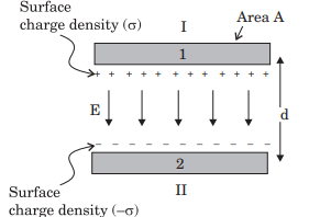
• Capacitor: The system of two conductors separated by an insulator is called a capacitor. The device which is used to store charge is known as a capacitor. The applied voltage and size of the capacitor decides the amount of charge that can be stored i.e., Q = CV
Two similar connecting plates are placed in the capacitor in front of each other where one plate is connected to the positive terminal and the other plate is connected to the negative terminal.
• Capacitance: The ratio of the magnitude of the charge stored on the plate to the potential difference between the plates is called capacitance. It is written as:
C=Q/∆V
Size, shape, medium and other conductors in the surroundings influence the capacitance of a conductor. Its S.I. unit is Farad.
1F = 1CV–1 For a parallel plate capacitor (with a vacuum between the plates), C=ε0AD
where A is the area of each plate and d in the separation between the parallel plates.
Source: Kapdec.com
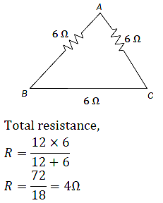
Example: A wire of resistance 18Ω is divided into three equal parts. These parts are connected in the side of the triangle, the equivalent resistance of any two corners of the triangle will be _______
Solution:
To find equivalent resistance across
BC, AB and AC is in series
R’ = 6 + 6 = 12Ω
12 Ω and 6 Ω is in parallel

Source: Kapdec.com
Source: Kapdec.com
Key points:
Resistivity:
- Resistivity is a measure of how strongly a material opposes the flow of electric current.
- It is represented by the Greek letter rho (ρ) and is measured in ohm-meters (Ω*m).
- Materials with high resistivity are poor conductors of electricity, while those with low resistivity are good conductors.
- Resistivity is affected by factors such as temperature, impurities, and the physical structure of the material.
Resistance:
- Resistance is a measure of how much a material resists the flow of electric current.
- It is represented by the symbol R and is measured in ohms (Ω).
- Resistance is determined by both the resistivity of the material and the dimensions of the object through which the current is flowing.
- Resistors are components designed to introduce a specific amount of resistance into a circuit.
Capacitance:
- Capacitance is the ability of a system to store an electric charge.
- It is represented by the symbol C and is measured in farads (F).
- Capacitance is determined by the geometry and materials of the system and is affected by factors such as the distance between charged objects and the dielectric constant of the material between them.
- Capacitors are components designed to introduce a specific amount of capacitance into a circuit. They can be used to store electrical energy or filter out certain frequencies of a signal.
Series Combination:
- Resistors in series are connected end to end, with the current flowing through each resistor in turn.
- The total resistance of a series combination is equal to the sum of the individual resistances.
- The total voltage across the combination is equal to the sum of the voltage drops across each resistor.
- The current through each resistor is the same in a series combination.
- The power dissipated by each resistor can be calculated using Ohm’s law (P = I2R) or the voltage drop and current through each resistor (P = VI).
Parallel Combination:
- Resistors in parallel are connected across a common voltage source, with the current dividing among the resistors.
- The total resistance of a parallel combination is less than the smallest individual resistance.
- The total current flowing into the parallel combination is equal to the sum of the currents flowing through each resistor.
- The voltage drop across each resistor is the same in a parallel combination.
- The power dissipated by each resistor can be calculated using Ohm’s law (P = V2/R) or the current through and voltage drop across each resistor (P = V*I).
