KAPDEC® | Elite STEM Learning Platform | https://kapdec.com
Unit: Geometric and Physical Optics
Chapter: Images from Lenses and mirrors
Reference: AP Physics Algebra, Geometric and Physical Optics, Images from Lenses and mirrors, the image formed by Plane Mirror, Reflection of light by spherical Mirrors, Few Basic terms related to Spherical Mirror, Concave Mirror Image formation, Image formation by a Convex Mirror, Uses of convex mirrors, Mirror Formula & Magnification, Refraction at a spherical surface, Refraction by a lens, Power of a lens, Combination of thin lenses in contact
After studying this chapter, you should be able to,
- state the Image formed by Plane Mirror
- explain the concepts of Refraction at a spherical surface:
- know the formula of magnification
- know the concept of the Combination of thin lenses
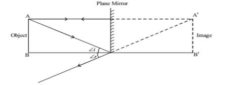
The image formed by Plane Mirror (Plane reflecting surface)
Source: Kapdec.com
1. Virtual (imaginary) & Erect: The image that do not form on screen.
Real images can be recorded on the screen.
2. Laterally inverted (The left side of the object appear on the right side of the image)
3. The size of the image is equal to that of the object.
4. The image formed is as far behind the mirror as the object is in front of it.
Uses of Plane Mirror:
A plane mirror is used in looking glasses, in the construction of kaleidoscopes, telescopes, sextants, periscopes etc., for seeing around the corners, as deflectors of light etc.
Reflection of light by spherical Mirrors
Mirrors, whose reflecting surfaces are curved inward or outward spherically are called spherical mirrors.
For example – Spoon
Source: Kapdec.com
The curved surface of the shinning spoon can be considered as curved mirror.
Source: Kapdec.com
Source: Kapdec.com
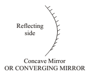
If it is curved inward
Source: Kapdec.com
Act as a concave mirror
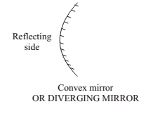
If it is curved outward
Source: Kapdec.com
Act as a convex mirror.
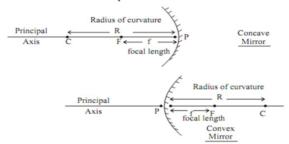
Few Basic terms related to Spherical Mirror
Source: Kapdec.com
- Principal axis: Line joining the pole and centre of curvature of the spherical mirror.
- Pole: The geometrical central point of the reflecting spherical surface. (aperture), denoted by (P).
- Aperture: The width of the reflecting spherical surface.
- Centre of curvature: The centre of the hollow glass sphere of which the spherical mirror is a part is called as the centre of curvature.
- The radius of curvature: The distance between the pole and the centre of curvature. i.e.
- PC = R or The radius of the hollow sphere of which the mirror is a part.
- Focus point: The point on the principal axis, where all parallel rays meet after reflection is called as Principal Focus or Focus. It is denoted by the letter ‘F’.
- Focal length: The distance between the pole and focus point i.e. PF = f
- Relationship between focal length and Radius of curvature.
Source: Kapdec.com
Image Formation by Spherical Mirror
Before we learn the formation of the image or ray diagram, let us go through a few tips
(a) Remember, a ray of light which is parallel to the principal axis always passes through focus (meet at focus) or vice-versa.
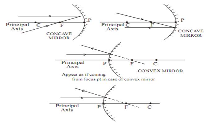
Source: Kapdec.com
(b) A ray of light which passes through the centre of curvature (it is also known as normal at the point of incidence on the spherical mirror) will retrace its path after reflection.
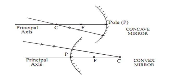
Source: Kapdec.com
(c) A ray of light falling on a pole gets reflected at the same angle on the other side of the principal axis.
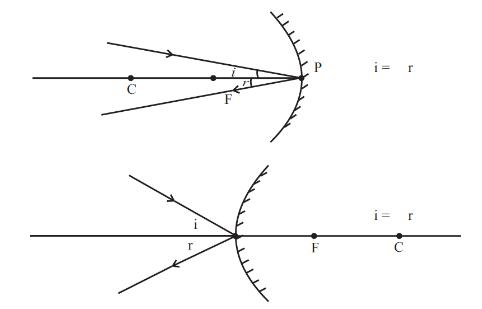
Source: Kapdec.com
Note: A ray of light passes through the centre of curvature of the reflecting spherical surface and always acts as normal at the point of incidence. If we know the normal, we can draw the angle of incidence and angle of reflection.
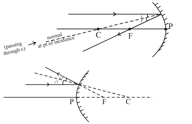
Source: Kapdec.com
Note 1: The image will only form when two or more rays meet at a point. Image formation by a concave mirror for different positions of the object.
Concave Mirror Image formation
The formation of the image depends upon the position of the object. There are six possibilities for the position of the object in the case of the concave mirror.
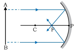
1. When the object is placed at infinity,
2. When the object is placed beyond C (centre of curvature)
3. When the object is placed at C
4. When the object is placed between C and F (principal focus)
5. When the object is placed at F
6. When the object is placed between F and P (Pole)
When the Object is at Infinity
In this condition, we consider two rays parallel to the principal axis originating from the object. These rays after reflection converge and form an image at F, the principal focus of the mirror, in front of the mirror. The image thus formed is highly diminished, point size, real and inverted.
Source: Kapdec.com
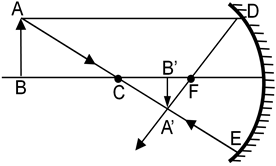
The Object is Placed Beyond C
In this situation, we consider two different rays emerging from the object. One is parallel to the principal axis and the other is directed towards the centre of curvature of the mirror. These rays after reflection form an image between the centre of curvature (C) the focus (F). The image thus formed is diminished, real and inverted.
Source: Kapdec.com
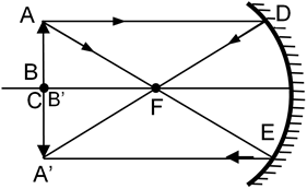
The Object is Placed at C
Here the two rays emerging from the object are one parallel to the principal axis and the other passing through the focus of the mirror. These rays after reflection form an image at point C. The image formed has the same size as that of the object and it is real and inverted.
Source: Kapdec.com
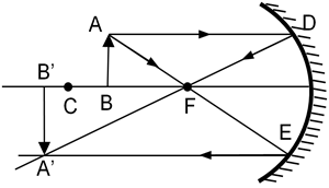
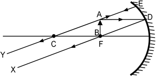
The Object is Placed Between C and F
Here the two rays considered are one parallel to the principal axis and the other passing through the principal focus of the concave mirror. The image is formed beyond C. The image is larger compared to the size of the object and it is real and inverted.
Source: Kapdec.com
The Object is Placed at F
The rays considered here are one parallel to the principal axis and the other passing through the centre of curvature of the mirror. This results in the formation of a highly enlarged image which is real and inverted, at infinity.
Source: Kapdec.com
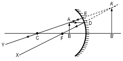
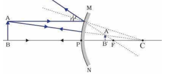
The Object is Placed Between F and P
The rays considered here are, one going parallel to the principal axis and the other passing through the centre of curvature of the mirror. The image formed here is virtual and erect and it is larger than the object.
Source: Kapdec.com
Image Formation Tabular Data
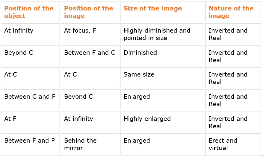
Source: Kapdec.com
Uses of Concave Mirror:
Concave minor is used as a reflector in searchlights, headlight of motor cars and projectors etc., for converging solar radiation in solar cookers, in floodlights to obtain a divergent beam of light to illuminate buildings, in reflecting telescopes etc
Image formation by a Convex Mirror
(i)When the object is at infinity
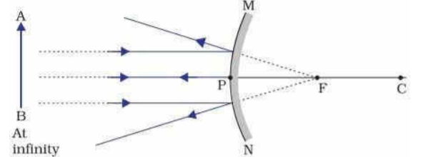
Source: Kapdec.com
→
Source: Kapdec.com
Image is formed at focus F behind the mirror
→ Image is highly diminished or point sized
→ Image is virtual and erect
(ii)When the object is between infinity and the pole P of the mirror
Source: Kapdec.com
→ Image is formed between P and F behind the mirror
→ Image is diminished
→ Image is virtual and erect
Uses of convex mirrors
(i)Convex mirrors are used as rear-view mirrors in vehicles because
→ they always give an erect and diminished image
→ they give a wider field of view as they are curved outwards.
(ii) They are used in shops as security mirrors.
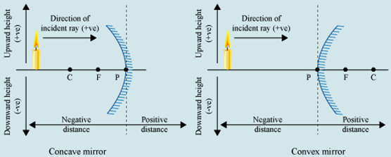
Sign Conventions
The new Cartesian sign convention is used to give sign convention used for spherical mirrors. The conventions are as follows-
1. The object is always placed to the left of the mirror.
2. All distances parallel to the principal axis are measured from the pole of the mirror.
3. All the distances measured to the right of the origin (along + x-axis) are taken as positive while those measured to the left of the origin (along – x-axis) are taken as negative.
4. Distances measured perpendicular to and above the principal axis (along + y-axis) will be taken as positive.
5. Distances measured perpendicular to and below the principal axis (along –y-axis) will be taken as negative.
Source: Kapdec.com
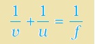
Mirror Formula & Magnification
Mirror Formula:
Source: Kapdec.com
Where: –
The distance of the object from its pole is called the object distance (u).
The distance of the image from the pole of the mirror is called the image distance (v).
The distance of the principal focus from the pole is called the focal length (f).
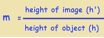
Magnification
If h is the height of the object and h’ is the height of the image, then the magnification m produced by a spherical mirror is given by
Source: Kapdec.com
The magnification m is also related to the object distance (u) and image distance (v). It can be expressed as:
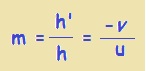
Source: Kapdec.com
A negative sign in the value of the magnification indicates that the image is real.
A positive sign in the value of the magnification indicates that the image is virtual.
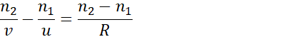
Refraction at a spherical surface:
n2v–n1u=n2–n1R
Source: Kapdec.com
Gives us a relation between object and image distance in terms of the refractive index of the medium and the radius of curvature of the curved spherical surface. It holds for any curved spherical surface.
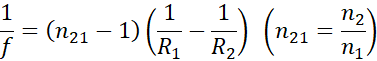
Refraction by a lens:
1f=n21-11R1–1R2 n21=n2n1
Source: Kapdec.com
This equation is known as the lens maker’s formula.
It is useful to design lenses of desired focal length using surfaces of suitable radii of curvature. Note that the formula is true for a concave lens also.
.
Power of a lens:
P=1 f

Source: Kapdec.com
The SI unit for power of a lens is dioptre (D): 1D = 1m–1. The power of a lens of a focal length of 1 metre is one dioptre.
The power of a lens is positive for a converging lens and negative for a diverging lens. Thus, when an optician prescribes a corrective lens of power + 2.5 D, the required lens is a convex lens of focal length + 40 cm.
A lens of power of – 4.0 D means a concave lens of focal length – 25 cm.
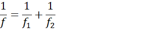
Combination of thin lenses in contact:
1f=1f1+1f2
Source: Kapdec.com
The derivation is valid for any number of thin lenses in contact. If several thin lenses of focal lengths f1, f2, f3, …. are in contact, the effective focal length of their combination is given by
In terms of power, the above equation can be written as
P=P1+P2+P3…………..
Source: Kapdec.com
where P is the net power of the lens combination.
Example: Suppose the object’s distance is 4cm in front of the mirror. The image distance is 16 cm in front of the mirror. Find Magnification.
Solution:
Given,
Object distance= u = -4cm
Image distance= v = -16cm
u and v are negative because they are in front of the mirror.
So, magnification m is given by:
m=-vU
Source: Kapdec.com
m=-(-16)-4
Source: Kapdec.com
=-4
Lenses:
Convex lenses: Convex lenses are thicker at the centre and thinner at the edges. They converge parallel rays of light and are commonly known as converging lenses.
Concave lenses: Concave lenses are thinner at the centre and thicker at the edges. They diverge parallel rays of light and are known as diverging lenses.
Focal point: A lens has a principal focal point, which is the point where parallel rays of light converge (for a convex lens) or appear to diverge from (for a concave lens) after passing through the lens.
Focal length: The distance between the centre of a lens and its focal point is called the focal length. It is denoted by ‘f.’
Real image: A real image is formed when light rays converge and can be projected onto a screen. It is formed by convex lenses when the object is placed beyond the focal point.
Virtual image: A virtual image is formed when light rays appear to diverge from a point. It cannot be projected onto a screen. It is formed by convex lenses when the object is placed closer than the focal point and by concave lenses in all cases.
Magnification: The magnification produced by a lens is the ratio of the image height to the object height. It can be calculated as the ratio of the image distance to the object distance.
Mirrors:
Concave mirrors: Concave mirrors curve inward, and the reflecting surface bulges inwards. They can form both real and virtual images depending on the position of the object.
Convex mirrors: Convex mirrors curve outward, and the reflecting surface bulges outwards. They always form virtual, diminished, and upright images.
Focal point: A concave mirror has a principal focal point where parallel rays of light converge after reflection. The focal point of a convex mirror is the point where parallel rays of light appear to diverge from after reflection.
Focal length: The distance between the centre of a mirror and its focal point is called the focal length. It is denoted by ‘f.’
Real image: A real image is formed by concave mirrors when the object is placed beyond the focal point. It is inverted and can be projected onto a screen.
Virtual image: A virtual image is formed by concave mirrors when the object is placed between the focal point and the mirror or by convex mirrors in all cases. It is upright and cannot be projected onto a screen.
Magnification: The magnification produced by a mirror is the ratio of the image height to the object height. It can be calculated as the ratio of the image distance to the object distance.
