Unit: Electric Circuits
Chapter: Steady-state direct-current circuits with batteries and resistors only
Reference: AP Physics Electricity and Magnetism, Electric Circuits, Steady-state direct-current circuits with batteries and resistors only, Resistors in Series, Resistors in Parallel
After studying this chapter, you should be able to,
- Know the concept of resistor in series and parallel
- obtain equivalent resistance for a series and parallel combination of resistors;
- solve the resistor and battery combination circuit problem
Resistors in Series:
Identifying series and parallel connections:
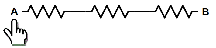
If you can move your finger along the wires from A to B without passing a junction, i.e., without ever having a choice of which wire to follow, the components are connected in series.
In contrast:
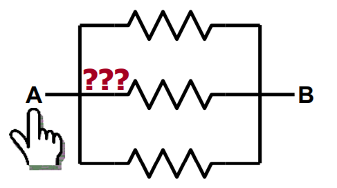
If you ever have a choice of which wire to follow when moving from A to B, the circuit elements are not in series.
If each element provides an alternative path between the same points A and B, the elements are in parallel.
Resistors are in series,
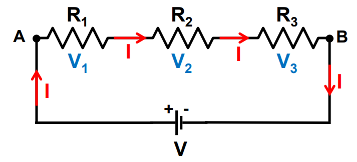
Current: same current flows through all resistors (conservation of charge: all charge entering the series of resistors at A must leave it at B)
Voltage: voltages in a series add up VAB=V1+V2+V3
In the electric circuit shown above, let I be the current through the circuit. The current through each resistor is also I. It is possible to replace the three resistors joined in series by an equivalent single resistor of resistance R, such that the potential difference V across it, and the current I through the circuit remains the same. Applying the Ohm’s law to the entire circuit, we have
V = I R
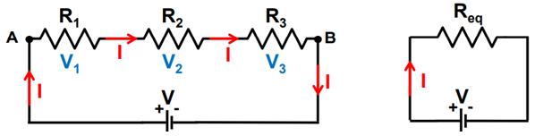
Replace the series combination by a single “equivalent” resistor (producing same total voltage for same current)
We can conclude that when several resistors are joined in series, the resistance of the combination Rs equals the sum of their individual resistances, R1, R2, R3, and is thus greater than any individual resistance.
Resistors in Parallel:
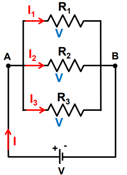
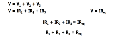
Current: current I split into currents I1, I2, I3
I = I1+ I2+ I3 (conservation of charge)
Voltage: Voltage drops across all three resistors are identical VAB= V1= V2= V3 (conservation of energy)
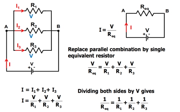
Thus, we may conclude that the reciprocal of the equivalent resistance of a group of resistances joined in parallel is equal to the sum of the reciprocals of the individual resistances.
We have seen that in a series circuit the current is constant throughout the electric circuit. Thus, it is obviously impracticable to connect an electric bulb and an electric heater in series, because they need currents of widely different values to operate properly. Another major disadvantage of a series circuit is that when one component fails the circuit is broken and none of the components works. If you have used ‘fairy lights’ to decorate buildings on festivals, on marriage celebrations etc., you might have seen the electrician spending lot of time in trouble-locating and replacing the ‘dead’ bulb each has to be tested to find which has fused or gone. On the other hand, a parallel circuit divides the current through the electrical gadgets. The total resistance in a parallel circuit is decreased. This is helpful particularly when each gadget has different resistance and requires different current to operate properly.
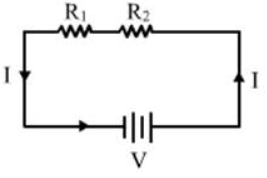
Example 1: With the help of a circuit diagram, deduce the equivalent resistance of two resistances connected in series.
Solution:
Let the current in the circuit be I amperes and the battery be of strength V volts. Let the combined resistance of the three resistors be R ohms.
Therefore, according to Ohm's law, we have
V=IR —- (i)
We know that when resistors are connected in series, the current with a battery of V volts.
V1=I×R1 ——- (ii)
V2 =I×R2 —— (iii)
Let the potential difference across R1 is V1 and the potential difference across R2 is V2
V=V1+V2——— (iv)
From equation (i), (ii), (iii) and (iv) we get.
IR= I×R1+ I×R2
R= R1+ R2
Example 2: A battery of 9 V is connected in series with resistors of 0.2 W, 0.3 W, 0.4 W, 0.5 W and 12 W, respectively. How much current would flow through the 12 W resistor?
Solution: All the resistors are connected in series.
Thus, equivalent resistance, R = 0.2Ω + 0.3Ω + 0.4Ω + 0.5Ω + 12 = 13.4 Ω
Potential difference, V = 9 V
And, Current, I=?
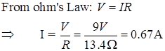
Since in series connection, the current throughout the circuit is same. Therefore, 0.67 A will flow through the 12 Ω resistor.
Example3 : Two lamps, one rated 100 W at 220 V, and the other 60 W at 220 V, are connected in parallel to electric mains supply. What current is drawn from the line if the supply voltage is 220 V?
Solution: Given the power of the two lamps, we will calculate the resistances R1 and R2 of two lamps separately.
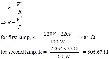
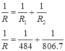
Now, the two lamps of resistances 484Ω and 806.7Ω are connected in parallel.
So, the combined resistance of two lamps can be calculated as follows:
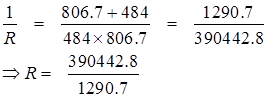
Total resistance, R= 302.5Ω
Current drawn from the line can now be calculated by using Ohm's law as follows:
Thus, the current drawn from the line is 0.72 A
Key points:
Series Combination:
- Resistors in series are connected end to end, with the current flowing through each resistor in turn.
- The total resistance of a series combination is equal to the sum of the individual resistances.
- The total voltage across the combination is equal to the sum of the voltage drops across each resistor.
- The current through each resistor is the same in a series combination.
- The power dissipated by each resistor can be calculated using Ohm's law (P = I2R) or the voltage drop and current through each resistor (P = VI).
Parallel Combination:
- Resistors in parallel are connected across a common voltage source, with the current dividing among the resistors.
- The total resistance of a parallel combination is less than the smallest individual resistance.
- The total current flowing into the parallel combination is equal to the sum of the currents flowing through each resistor.
- The voltage drop across each resistor is the same in a parallel combination.
- The power dissipated by each resistor can be calculated using Ohm's law (P = V2/R) or the current through and voltage drop across each resistor (P = V*I).