Unit: Magnetism and Electromagnetic Induction
Chapter: Monopole and Dipole Fields and Magnetic Flux
Reference: AP Physics Algebra, Circular Motion and Gravitation, Magnetism and Electromagnetic Induction, Monopole and Dipole Fields and Magnetic Flux, Monopole Field, Dipole Field, Earth’s Magnetism, Magnetization and magnetic field, Magnetic properties of materials, Curie’s law, Permanent magnets, Electromagnets, Electromagnetic Induction Laws, The Experiments of Faraday and Henry, Magnetic Flux, Faraday’s Law of Induction, Lenz’s law and Conservation of Energy, Motional Electromotive Force, Energy Consideration: A Quantitative Study
After studying this chapter, you should be able to,
- state the Monopole and dipole fields
- explain the concepts of Magnetization and magnetic field:
- state the laws of Electromagnetic Induction
Monopole Field:
- In physics, a monopole refers to a hypothetical magnetic charge that exists alone without any opposite charge.
- Unlike electric charges, which can exist as positive or negative charges, magnetic monopoles have not been observed in isolation.
- According to theoretical physics, if magnetic monopoles exist, they would explain certain fundamental symmetries in the laws of electromagnetism.
- A monopole field, if it exists, would diverge or converge from a single point or source, similar to the way electric fields emanate from electric charges.
- The existence of magnetic monopoles would have profound implications for our understanding of fundamental physics and could unify the theories of electromagnetism and quantum mechanics.
- The strength of the monopole field at a point in space is given by Coulomb's Law for magnetic charges: F = (μ₀ / 4π) * (qm / r²)
where F is the force exerted by the monopole field, μ₀ is the permeability of free space, qm is the magnetic charge, and r is the distance from the magnetic charge.
Dipole Field:
- A dipole field is a type of magnetic or electric field that originates from a dipole, which consists of two equal and opposite charges or poles separated by a distance.
- In a magnetic dipole, the poles are the North and South poles, whereas in an electric dipole, the charges are positive and negative.
- The strength of the field decreases with distance from the dipole according to the inverse square law.
- The field lines of a dipole field form closed loops, extending from the North pole to the South pole or from the positive charge to the negative charge.
- Dipole fields are commonly encountered in various physical systems, such as bar magnets, electric dipoles in molecules, and Earth's magnetic field, which approximates a magnetic dipole
- For the magnetic dipole moment (m) and the distance (r) from the dipole, the magnetic field strength (B) is calculated using the formula:
B = (μ₀ / 4π) ×![]() [(2m / r³) ×
[(2m / r³) ×![]() cos(θ)]
cos(θ)]
where μ₀ is the permeability of free space, θ is the angle between the axis of the dipole and the direction from the dipole to the point, and cos(θ) accounts for the orientation of the dipole.
- For the electric dipole moment (p) and the distance (r) from the dipole, the electric field strength (E) is given by the formula:
E = (1 / 4πε₀) ×![]() [(2p / r³) ×
[(2p / r³) ×![]() cos(θ)]
cos(θ)]
where ε₀ is the permittivity of free space.
Earth’s Magnetism:
• The earth’s magnetism is of the order of 10–5 T. Its strength is different at different places. The pole near to geographic north pole is called the north magnetic pole and the pole near to geographic south pole is called the south magnetic pole. The magnetic of field on the Earth's surface is
4 ×![]() 10–5 T.
10–5 T.
• There are three elements of the earth’s magnetic field which are used to specify the magnetic field of the earth's surface – the horizontal component, the magnetic declination and the magnetic dip.
• The magnetic field of a bar magnet tilted 11° from the spin axis of the Earth is in the same direction as the Earth’s magnetic field.
Magnetization and magnetic field:
• The magnetization M is equal to its magnetic moment per unit volume
M =mnet/V
• The magnetic intensity H is defined as the amount of magnetic flux in a unit area perpendicular to the direction of magnetic flow.
H = B0μ0![]()
• The magnetic field B in the material is given by,
B = m0(H + M)
• The degree of magnetization of a material in response to an applied magnetic field is denoted
as magnetic susceptibility. It is given by
X = MH![]()
μ![]() =μ0/μr
=μ0/μr
Where μr![]() = 1 + x
= 1 + x
Magnetic properties of materials:
Magnetic Materials are broadly classified as paramagnetic, diamagnetic and ferromagnetic materials. For paramagnetic materials X is positive and is small, for diamagnetic materials X is negative and lies between 0 and -1 and for ferromagnetic materials X is positive and large.
![]()
Ferromagnetic materials show the property of hysteresis.
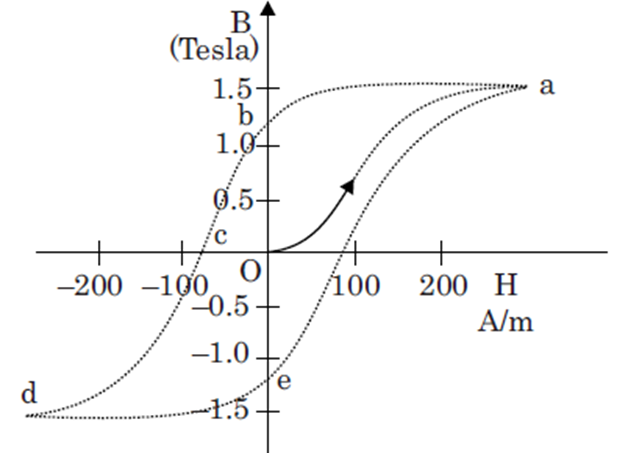
Magnetic hysteresis loop
The magnetic hysteresis loop is the B-H curve for ferromagnetic materials
Curie’s law:
The intensity of magnetization I of a paramagnetic material varies directly to the strength of the external magnetic field H, called magnetizing field and is inversely proportional to the absolute temperature of the material.
X = CT![]() where C is Curie constant.
where C is Curie constant.
Permanent magnets:
• Permanent magnets are those substances which at room temperature retain their ferromagnetic
property.
• An iron rod held in the north-south direction and if it is hammered repeatedly, it will become a permanent magnet.
• It can also be made by placing a ferromagnetic rod in a solenoid and passing a current through it.
The rod gets magnetized by the magnetic field of the solenoid.
• A material having high permeability, high coercivity, and high retentivity could be suitable for permanent magnets.
Electromagnets:
• A solenoid having a core of iron with wire wrapped around it is called an electromagnet.
• Ferromagnetic materials are used for the core of electromagnets.
• Some of the applications of electromagnets are loudspeakers, electric bells, and telephone diaphragms.
Electromagnetic Induction Laws
• Electromagnetic Induction is the one in which-by-which electric current is generated with the help of a magnetic field.
• The Experiments of Faraday and Henry
The observations from the experiments of Faraday and Henry concluded that it is the relative motion between the magnet and the coil that is responsible for the generation or induction of the electric current in the coil.
• Magnetic Flux
It is the number of field lines cutting through a surface area A defined by the unit area vector. The magnetic flux that passes through a plane of area A and has a uniform magnetic field B, is given by, ∅B= B.A = B/A cosθ where θ is the angle between magnetic field B and Area A. Magnetic flux is a scalar quantity and its SI unit is Weber.
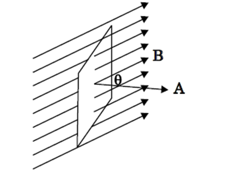
Field lines in a magnetic field
Faraday’s Law of Induction
• Faraday’s First Law: Whenever a conductor is placed in a varying magnetic field, there is an induced emf and if the conductor circuit is closed, there is an induced current.
• Faraday’s Second Law: This law of electromagnetic induction states that the magnitude of the induced emf in a circuit is equal to the time rate of change of magnetic flux through the circuit.
Mathematically, the induced emf is given by
ε![]() =-d∅B/dt
=-d∅B/dt
the negative sign indicates the direction of the induced emf and hence the direction in a closed loop.
Lenz’s law and Conservation of Energy
The Lenz’s law states that the polarity of induced emf is such that it tends to produce a current which opposes the change in magnetic flux that produced it.
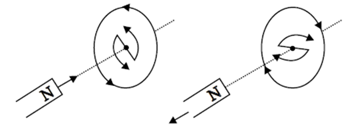
Lenz’s law
Motional Electromotive Force
The relationship between induced emf and a wire moving at a constant speed v is given by
ε![]() = Blv
= Blv
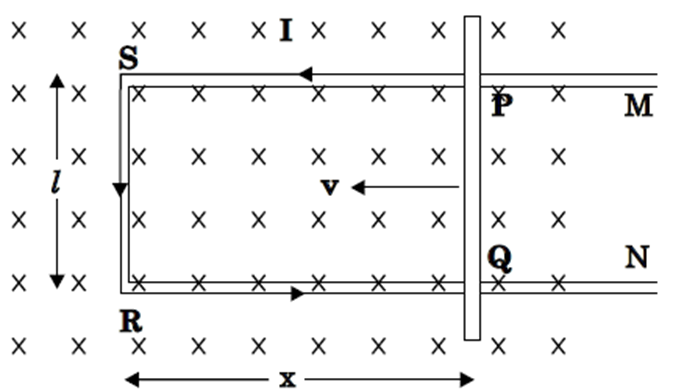
Energy Consideration: A Quantitative Study
• ‘r’ is the resistance of the movable arm PQ of the rectangular conductor. Assume that the remaining arms QR, RS, SP have negligible resistance compared to r. In the presence of a magnetic field, there will be a force on the arm AB. This force I(l×![]() B) is outwards directed in a direction opposite
B) is outwards directed in a direction opposite
to the velocity of the rod.
The magnitude of force is
F= B2I2/Vr
Magnitude to push arm PQ = Fv =B2I2V/2r
Energy Consideration in a Magnetic Field
Example: Two circuits have a coefficient of mutual induction of 0.09 ℎ𝑒𝑛𝑟𝑦. Average e.m.f. induced in the secondary by a change of current from 0 to 20 𝑎𝑚𝑝𝑒𝑟𝑒 in 0.006 𝑠𝑒𝑐𝑜𝑛𝑑 in the primary will be ________
Solution:
We know that,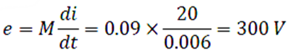
Key points:
- Faraday's Law of Electromagnetic Induction: This law states that the induced EMF in a closed loop is directly proportional to the rate of change of magnetic flux through the loop. Mathematically, it can be expressed as E = -dΦ/dt where E is the induced EMF, Φ is the magnetic flux and dt/dt represents the change in time.
- Lenz's Law: Lenz's law is an important consequence of Faraday's law. It states that the direction of the induced current in a conductor will always be such that it opposes the change producing it. In other words, the induced current creates a magnetic field that opposes the change in the magnetic field causing it.
- Magnetic Flux: Magnetic flux is a measure of the number of magnetic field lines passing through a surface. It depends on the strength of the magnetic field and the area perpendicular to the magnetic field lines. The unit of magnetic flux is Weber (Wb).
- Magnetic Field: The magnetic field is a region in space where magnetic forces are experienced. It is produced by moving electric charges or by magnets. The strength and direction of the magnetic field can vary with time, causing changes in the magnetic flux.
- Induced EMF and Current: When a conductor is subjected to a changing magnetic field, an induced EMF is generated. If the conductor forms a closed loop, this induced EMF causes an induced current to flow in the loop.
- Transformer Operation: Electromagnetic induction is the principle behind the operation of transformers. A transformer consists of two coils, the primary coil and the secondary coil, wound around a common iron core. When an alternating current (AC) flows through the primary coil, it produces a changing magnetic field, which induces a voltage in the secondary coil through electromagnetic induction.
- Applications: Electromagnetic induction has numerous practical applications, including electric generators, transformers, induction cooktops, electric motors, magnetic levitation systems, and wireless charging technologies.