Unit: Dynamics
Chapter: Free-Body Diagrams
Reference: AP Physics Algebra, Dynamics, Free-Body Diagrams, Conservation of momentum, Free Body Diagram, how to draw FBD of Figure, Apparent Weight of a Body in a Lift, Equilibrium of Particles
After studying this chapter, you should be able to:
- State the conservation of momentum
- to draw free body diagram of Figure:
Conservation of momentum
If no external force acts on a system (called isolated) of constant mass, the total momentum of the system remains constant with time.
- According to this law for a system of particles
F =dp/dt
In the absence of external force F = 0 then P = constant.
i.e., P = p1 + p2 + p3+ …….= constant.
(2) Law of conservation of linear momentum is independent of the frame of reference through linear momentum depends on the frame of reference.
(3) Practical applications of the law of conservation of linear momentum
- When a man jumps out of a boat on the shore, the boat is pushed slightly away from the shore,
- A person left on a frictionless surface can get away from it by blowing air out of his mouth or by throwing some object in a direction opposite to the direction in which he wants to move,
- Recoiling of a gun-Tor bullet and gun system, the force exerted by the trigger will be internal so the momentum of the system remains unaffected.
Free Body Diagram:
Free Body Diagram In this diagram the object of interest is isolated from its surroundings and the interactions between the object and the surroundings are represented in terms of forces.
A diagram showing all the forces acting on a body is called a free-body diagram.
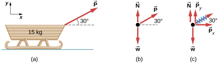
How to draw FBD of Figure:
Steps:
- Free the body (remove all the contacting surfaces, ropes etc.) but remember where they were attached.
- Show the contact forces.
- Show the non-contact forces.
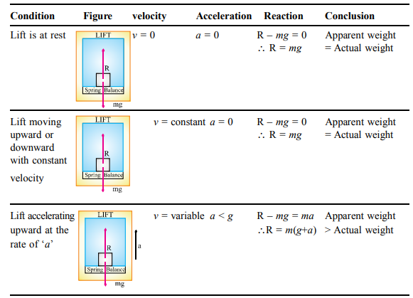
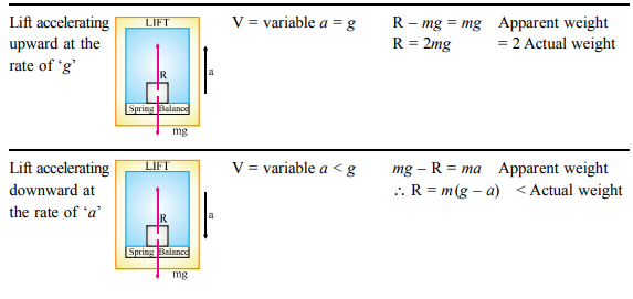
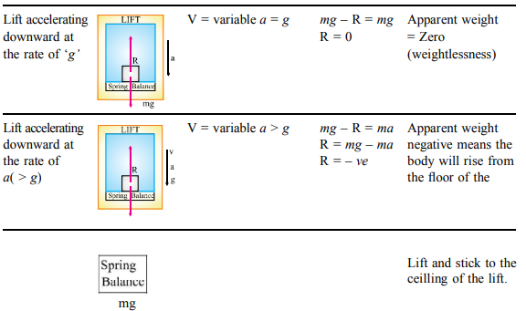
Apparent Weight of a Body in a Lift
When a body of mass m is placed on a weighing machine which is placed in a lift, then the actual weight of the body is mg. This acts on a weighing machine which offers a reaction R given by the reading of the weighing machine. The reaction exerted by the surface of contact on the body is the apparent weight of the body.
Equilibrium of Particles:
A system is said to be in equilibrium when it is not accelerated which automatically means that the net force on it should be equal to zero i.e.
Fx=0
Fy=0
Fz=0
Definition: When the resultant of all forces acting on a particle is zero, the particle is in equilibrium.
Condition: satisfied Newton's first law which states that a particle is in equilibrium if it is at rest or moves in a straight line with a constant speed provided that no external forces exert on it.
Example 1:
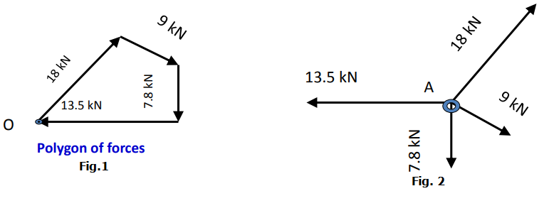
Fig.1 Polygon of forces ends at the same point as the start point. Which means the resultant force of forces in the system is zero. i.e., the particle is in equilibrium
Fig.2 Four forces acting on a particle
Example 2:
A mass of 6 kg is suspended by a rope of length 2 m from the ceiling. A force of 50 N in the horizontal direction is applied at the midpoint P of the rope, as shown. What is the angle the rope makes with the vertical in equilibrium? (Take g = 10 m s-2). Neglect the mass of the rope.
Answer
Figures 5.8(b) and 5.8(c) are known as free-body diagrams. Figure 5.8(b) is the free-body diagram of W and Fig. 5.8(c) is the free-body diagram of point P.
Consider the equilibrium of the weight W. Clearly, T2 = 6 × 10 = 60 N.
Consider the equilibrium of point P under the action of three forces – the tensions T1 and T2, and the horizontal force 50 N. The horizontal and vertical components of the resultant force must vanish separately:
T1 cos q = T2 = 60 N
T1 sin q = 50 N
which gives that
tan q = 56![]() or q = tan–1 56
or q = tan–1 56![]() = 400
= 400
Note the answer does not depend on the length of the rope (assumed massless) nor on the point at which the horizontal force is applied.
Key points:
A free-body diagram (FBD) is a visual representation that shows all the external forces acting on an object, without including any internal forces or details of the object itself. It is a tool used in physics and engineering to analyze and understand the behaviour of an object or system under various external forces.
In a free-body diagram, the object is represented by a dot or a small box, and all the external forces acting on it are represented by arrows. The length and direction of the arrows represent the magnitude and direction of the force, respectively. The arrows are labelled with the corresponding force name, such as gravity, normal force, friction force, etc.
Free body diagrams are used to solve problems related to mechanics, such as finding the net force on an object, determining the acceleration of an object, or predicting the motion of an object under different conditions. They help to simplify complex problems by breaking them down into simpler components and analysing each one separately.